How to Make a Laser Beam Expander: Simple Guide
Have you ever tried to focus a laser for precision cutting, alignment, or optical experiments, only to find the beam too narrow or divergent to be effective? A laser beam expander solves this problem by increasing beam diameter and reducing divergence, enabling tighter focus and longer working distances. Whether you are building a DIY laser setup or optimizing an industrial system, knowing how to make a laser beam expander is a critical skill. This guide walks you through every step, from choosing between Keplerian and Galilean designs to assembling and testing your system using off-the-shelf optics.
Choose Between Galilean and Keplerian Designs
The first decision in building a beam expander is selecting the optical configuration. Two main types exist: Galilean and Keplerian. Your choice depends on laser power, space limits, and whether you need beam conditioning capabilities. Understanding the fundamental differences between these designs will help you make an informed decision for your specific application.
Galilean Design: Best for High Power
A Galilean beam expander uses a negative diverging lens followed by a positive converging lens. The input beam diverges after the first lens and is collimated by the second lens without forming an internal focus point. This design is ideal for high-power lasers because no focal point means no air ionization or plasma risk, and the overall length is shorter than a Keplerian design for the same magnification. However, you cannot insert a spatial filter in a Galilean system, which limits beam cleaning capability.
Keplerian Design: Add a Spatial Filter
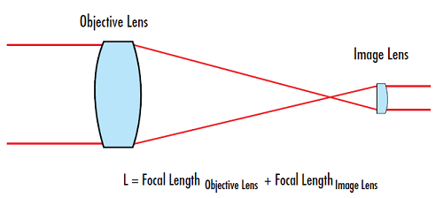
A Keplerian system uses two positive lenses separated by the sum of their focal lengths. The first lens focuses the beam to a real point, which the second lens re-collimates. This internal focus allows you to place a spatial filter for beam cleaning, removing noise and improving mode quality. The tradeoff is that high-power applications become risky due to air breakdown at the focal point. Keplerian designs are also longer and more complex to align. Choose Galilean for high-power diodes or fiber lasers, and use Keplerian only when beam purification is essential.
Calculate Magnification and Optical Track Length
Once you have chosen your design, determine the lens focal lengths based on desired magnification and space constraints. Proper calculations ensure your system fits within available space while achieving the required beam expansion.
Use the Magnification Formula
For any beam expander, magnification equals the positive lens focal length divided by the absolute value of the negative lens focal length. In a Galilean design, this means M equals f_positive divided by the absolute value of f_negative. For a 5X expansion, common pairs include negative 6 mm with positive 30 mm for 5X magnification and 36 mm track length, negative 12 mm with positive 60 mm for 5X magnification and 72 mm track length, or negative 15 mm with positive 75 mm which may exceed housing limits.
Match Optical Track to Space Limits
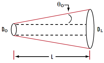
The optical track length equals the sum of the positive focal length and the absolute value of the negative focal length. However, mechanical length will be longer due to lens thickness and mounts. If your maximum space is 75 mm, avoid designs with optical lengths exceeding 72 mm. Longer tracks generally improve performance by reducing spherical aberration and improving wavefront fidelity, so prioritize longer focal length pairs when possible, even if they cost more.
Select Lenses with Proper Clear Aperture
Even perfectly calculated lenses fail if they clip the beam. Vignetting destroys beam quality, causing diffraction rings and power loss. Selecting the right aperture sizes is critical for maintaining beam integrity throughout the expansion process.
Size Lenses for Input and Output Beams
The negative lens must accept the full input beam diameter, while the positive lens must transmit the full expanded output beam. For a 3 mm input and 5X magnification, the output equals 3 times 5, which is 15 mm. This means the positive lens needs a clear aperture larger than 15 mm. Use lenses with at least 1.2 times the beam diameter to avoid edge effects and ensure clean beam transmission.
Choose Lens Shape and Orientation
Plano-singlets perform better than biconvex or biconcave lenses for beam expansion applications. Use plano-concave for the input lens and plano-convex for the output lens to reduce spherical aberration. Orient the plano side toward the input beam to balance optical errors. For example, a compatible stock combination includes a plano-concave negative lens at 12 mm focal length with 6 mm diameter and a plano-convex positive lens at 60 mm focal length with 25 mm diameter, yielding 5X magnification and 15 mm output beam suitable for 532 nm and 632.8 nm lasers.
Optimize with Optical Design Software
Never build blind. Use optical design software like Zemax to simulate performance before assembly. Simulation allows you to identify and correct issues before purchasing expensive components, saving time and money during the prototyping phase.
Set Up the System in Zemax
Input your parameters including wavelength, beam diameter, lens data with focal lengths, thicknesses, and materials. Set aperture type to beam diameter and enable afocal image space for angular analysis. Add a dummy surface after the last lens to measure output collimation accurately.
Define Merit Function and Optimize
Optimize using key operands. RAED minimizes output ray angle to ensure collimation. REAY monitors beam height at input and output surfaces. RMS Wavefront Error should target less than lambda divided by 4 PV for diffraction-limited quality. Let the optimizer adjust lens spacing to find the optimal configuration.
Review Simulation Results
After optimization, verify that spot size approaches the Airy disk limit, wavefront error is less than lambda divided by 4 PV, and output beam is the expected diameter and perfectly collimated. These results confirm the design will perform as intended when built physically.
Assemble with Precision Mounts
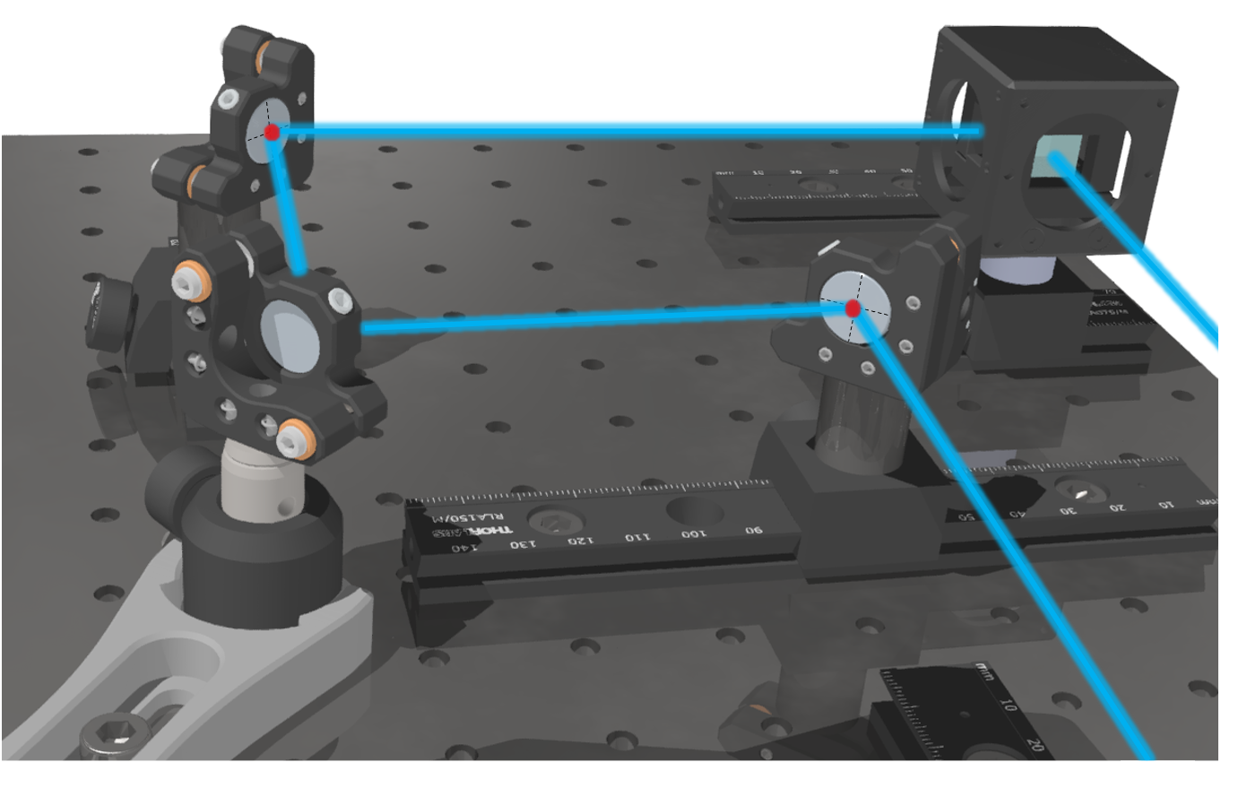
Even the best design fails with poor mounting. Mechanical stability ensures alignment and pointing accuracy. Investing in quality mounts pays dividends in system performance and long-term stability.
Use Adjustable Lens Cells
Mount lenses in kinematic lens holders or threaded lens tubes with retaining rings. Avoid over-tightening, as pressure causes stress birefringence and distortion. Quality mounts provide precise positioning while protecting the optics from mechanical stress.
Prevent Beam Wander
If using threaded focusers, rotation during adjustment can cause beam pointing drift. Use helicoid barrels or linear translation stages to move lenses without rotation. For critical applications, use micometer-driven stages for sub-millimeter control over lens positioning.
Allow Fine Divergence Tuning
Set lens separation slightly adjustable. Start with the initial gap based on calculated track length, then fine-tune position using beam profiling at distance. This compensates for manufacturing tolerances and ensures optimal collimation in the finished system.
Test for Collimation and Beam Quality
Never assume your beam is collimated. Verify it with proper measurement techniques. Thorough testing reveals issues that could compromise your application and confirms that the system meets specifications.
Measure Beam Diameter at Distance
Project the beam 10 to 50 meters and measure with a beam profiler, CCD camera, or burn paper for high-power low-precision applications. If diameter stays constant, the beam is well collimated. If it grows, there is slight divergence. If it shrinks, the beam is converging. Adjust lens separation until diameter is stable across measurement distances.
Quantify Wavefront Distortion
Use a shearing interferometer or Shack-Hartmann wavefront sensor to measure wavefront quality. Target less than lambda divided by 4 PV wavefront error to ensure diffraction-limited focusing performance. This specification guarantees minimal phase error and optimal focusability for your application.
Check Transmission Efficiency
Place a power meter before and after the expander to measure transmission. With AR coatings, expect greater than 90 percent transmission. Low transmission indicates reflections, misalignment, or coating mismatch. Compare measured values with theoretical loss estimates to identify problems early.
Inspect for Clipping
Look for diffraction rings in the beam profile, asymmetric intensity, or shadows. These indicate the beam is hitting lens edges. If observed, upgrade to larger aperture lenses to eliminate clipping and maintain beam quality.
Avoid Common Design Mistakes
Even experienced builders make avoidable errors. Understanding these pitfalls helps you sidestep problems that could derail your project or degrade performance.
Using Incorrect Lens Types
Biconvex and biconcave lenses increase spherical aberration significantly. Use plano-convex and plano-concave instead, and orient the plano side toward the input beam. This orientation balances optical errors and improves wavefront quality.
Ignoring Coating Specifications
Uncoated optics reflect approximately 4 percent per surface, which is enough to damage laser diodes and reduce efficiency. Use AR-coated lenses matched to your wavelength. MgF2 coatings work for broadband visible applications, while V-coatings are optimized for single wavelengths like 532 nm.
Overlooking Thermal Effects
In high-power systems, N-BK7 expands with heat and defocuses the beam. Use fused silica for powers exceeding 1 watt or for pulsed lasers. The higher cost is essential for maintaining stability and performance under thermal load.
Skipping Prototyping with Stock Optics
Do not custom-order lenses before testing. Use off-the-shelf components from suppliers to validate magnification, fit, and performance. Once validated, you can scale to production or optimize with custom components if needed.
Frequently Asked Questions About Laser Beam Expanders
What is the difference between Galilean and Keplerian beam expanders?
A Galilean beam expander uses a negative lens followed by a positive lens with no internal focus, making it suitable for high-power lasers. A Keplerian design uses two positive lenses with an internal focus that allows spatial filtering but risks air ionization at high power levels.
How do I calculate the magnification for my beam expander?
Magnification equals the focal length of the positive output lens divided by the absolute value of the negative input lens focal length. For example, a 60 mm positive lens with a 12 mm negative lens yields 5X magnification.
What lens coatings do I need for my laser wavelength?
Use AR-coated lenses designed for your specific wavelength. MgF2 coatings work well for broadband visible light, while V-coatings are optimized for single wavelengths like 532 nm green lasers or 632.8 nm HeNe lasers.
Why is my beam expander causing beam clipping?
Beam clipping occurs when lenses have insufficient clear aperture. Ensure your negative lens accommodates the full input beam and your positive lens is large enough for the expanded output beam. The rule of thumb is using lenses with at least 1.2 times the beam diameter.
Can I use a beam expander with any laser type?
You must consider laser power, wavelength, and beam quality when selecting a beam expander. Galilean designs work best for high-power diodes and fiber lasers. Keplerian designs suit lower-power applications where spatial filtering benefits beam quality.
How do I test if my beam expander is properly collimated?
Project the expanded beam 10 to 50 meters and measure the diameter at two points. If the diameter remains constant, the beam is collimated. If it grows, there is divergence. If it shrinks, the beam is converging. Adjust lens spacing to correct any issues.
Key Takeaways for Building a Laser Beam Expander
Building a high-quality laser beam expander requires careful attention to optical design, component selection, and assembly precision. Start by choosing between Galilean and Keplerian designs based on your power requirements and need for spatial filtering. Calculate magnification using the focal length ratio and ensure your optical track fits within mechanical space constraints. Select lenses with adequate clear aperture, preferring plano-convex and plano-concave shapes oriented with plano sides toward the input beam. Use optical design software like Zemax to simulate and optimize your design before building. Assemble with precision mounts that prevent beam wander and allow fine divergence tuning. Finally, test rigorously for collimation, wavefront quality, and transmission efficiency. By following these steps and avoiding common mistakes like using incorrect lens types or skipping coatings, you can build a diffraction-limited beam expander using readily available stock optics.