How to Make a Laser Detector: Simple DIY Guide
Laser detectors are more than just sci-fi gadgets. They are practical tools for security systems, automation projects, and interactive installations. Whether you are building a classroom demonstration or a competition scoring system, knowing how to make a laser detector opens doors to innovation. This guide walks you through two proven methods: a simple LDR-based alarm and an Arduino-powered color sensor detector that adapts to ambient light. You will learn exactly what components to use, how to wire them, and how to calibrate for reliable performance using affordable, off-the-shelf parts.
We will focus on real-world functionality, from detecting beam interruptions to identifying laser strikes by color temperature shifts. No prior experience is required. Each step is designed for clarity, safety, and success, even in changing lighting conditions.
Build a Simple LDR-Based Laser Detector
This method uses a light-dependent resistor to detect when a continuous laser beam is blocked. It is perfect for DIY security systems, interactive displays, or school science projects. The entire circuit costs under $10 and requires no coding.
Gather Required Components
You will need these basic parts to build your LDR laser detector. Collect everything before starting assembly.
• BC547 NPN transistor (acts as switching element)
• Light-dependent resistor (LDR)
• 100 kΩ resistor (pull-down to stabilize base voltage)
• LED (visual indicator)
• Buzzer (audible alarm)
• 9 V battery with connector
• Breadboard and jumper wires
• Optional: 220 Ω resistor for LED, potentiometer for sensitivity adjustment
Wire the BC547 Transistor Correctly
Place the BC547 NPN transistor on your breadboard with all three pins (Base, Collector, Emitter) in separate rows. The flat side should face you, with pins labeled: Left: Emitter (E), Middle: Base (B), Right: Collector (C). This orientation ensures correct signal flow through the transistor.
Connect the LDR between the Base and the Emitter. When light hits the LDR, its resistance drops, which prevents the transistor from turning on. This is the core detection mechanism.
Add Pull-Down and Output Components
Install a 100 kΩ resistor from the Base to the positive rail. This acts as a pull-down to keep the base stable in low-light conditions. Then connect the LED and buzzer in parallel configuration.
Wire the LED anode to the same node as the resistor and base. Connect the LED cathode to the Collector. For the buzzer, connect the positive terminal to the base/resistor node and the negative terminal to the Collector. This configuration ensures both output devices activate only when the transistor switches on.
Power and Test the Circuit
Link the positive rail to the 9 V battery positive terminal and the Emitter to the negative (GND) rail, which connects to the battery negative. Once powered, the circuit operates as a dark-activated alarm.
When the laser hits the LDR, resistance drops and the transistor stays off, keeping the LED and buzzer silent. When the beam is blocked, resistance increases, the base receives current, the transistor turns on, and the LED lights while the buzzer sounds. If nothing happens, check the polarity of the LED and buzzer and reverse if needed.
Optimize Sensitivity with Adjustments
Replace the fixed 100 kΩ resistor with a 100 kΩ potentiometer to fine-tune sensitivity. Turn the knob until the alarm triggers only when the beam is fully interrupted. For brighter LED indication without damage, add a 220 Ω resistor in series with the LED to allow higher current.
Shield the LDR from ambient light using a tube or enclosure. This simple step dramatically reduces false triggers from room lighting changes.
Mount as a Security Alarm
Position a laser pointer across a doorway or window so its beam continuously hits the LDR. Any intrusion breaks the beam and triggers the alarm immediately. Use multiple detector units for multi-point coverage across larger spaces. Secure all parts with tape or mounts to prevent misalignment over time.
Build an Arduino Laser Detector with Color Sensing

For higher accuracy, especially in variable lighting conditions, use an Arduino with a color sensor. This method detects lasers by their unique spectral signature rather than simple light absence. It is ideal for drone racing gates, laser tag scoring, or interactive art installations.
Connect TCS34725 to Arduino
Wire the Adafruit TCS34725 color sensor to the Arduino UNO using I²C protocol. Make these connections precisely.
• VCC → 5V
• GND → GND
• SDA → A4
• SCL → A5
Then connect an LED with 220 Ω resistor. The LED anode goes to Digital Pin 13, and the cathode connects to GND. This setup allows the microcontroller to read RGB values and trigger the LED on detection.
Disable Onboard Illumination LED
The TCS34725 has a built-in white LED that interferes with external light detection. You must disable it for accurate laser detection. Apply heat with a soldering iron to one terminal of the onboard LED until it detaches. Alternatively, fully desolder the component. Without this step, the sensor may fail to detect subtle laser-induced color shifts.
Focus Light with Lens and Diffuser
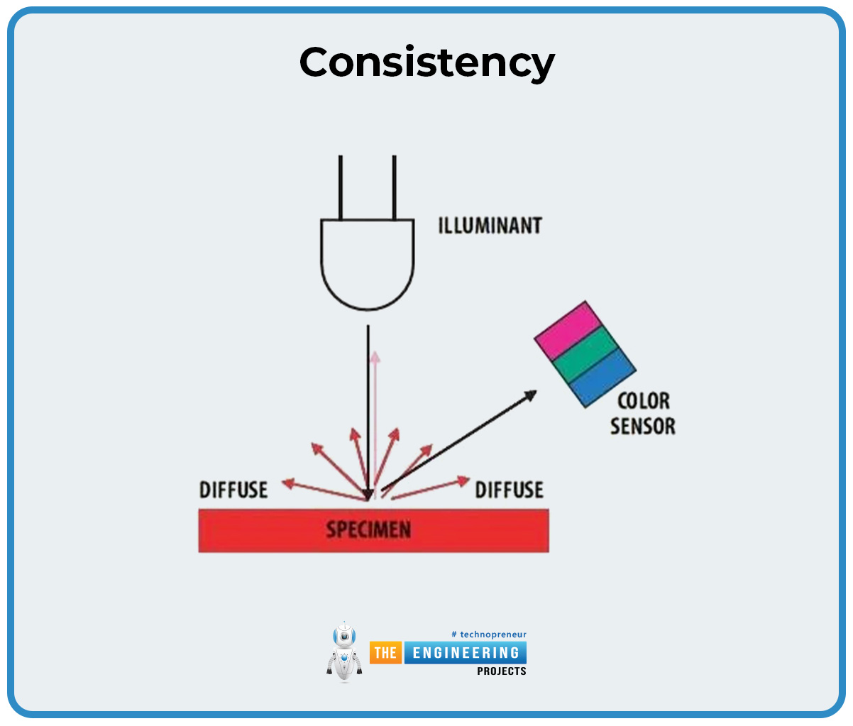
Use a magnifying lens inside a plastic tube to concentrate incoming light onto the sensor. Assemble these layers in order.
- Cover one end of the tube with tissue paper (acts as diffuser)
- Place the magnifying lens over the tissue paper
- Secure with a cap or hot glue
The diffuser prevents sensor saturation and evens out light distribution for more consistent readings.
Assemble Detector Housing

Print the STL detector mount from the GitHub repository. Attach the color sensor to a 4″x4″ backing board using mounting tape. Fix the board into the 3D-printed mount. Drill a hole in a 12″x12″ plywood base for the tube, then insert and hot glue the tube securely. Feed all wires through a side hole leading to the Arduino.
Ensure the lens faces the expected laser direction. Minor focus errors will not break functionality, but precise alignment improves detection reliability.
Calibrate Before First Use
On power-up, the Arduino runs a 10–20 second calibration phase. During this time, it takes ambient light samples and stores average RGB and color temperature values. Do not let the laser hit the sensor during this phase. After calibration, the LED turns on for 4 seconds, then turns off. Wait for this sequence to complete before testing detection.
Detect Laser via Color Temperature Shift
The code compares real-time readings to the stored baseline. A spike in red value or a sharp change in color temperature triggers detection. When a laser hits, the LED blinks once, then the system resets for the next detection.
Adjust the MAXTEMPDIFF constant in the code to change sensitivity. Lower values increase sensitivity while higher values reduce false alarms in bright sunlight.
Red lasers dominate the red channel, so you can use this characteristic for selective targeting of specific laser colors.
Install and Customize Detection Code
Download the full sketch from the GitHub repository. Install required libraries via Arduino IDE: Adafruit_TCS34725 and Adafruit_Sensor. Key code features include auto-calibration loop, real-time RGB monitoring, threshold-based trigger (MAXTEMPDIFF), and digital output control.
To increase sensitivity, lower the MAXTEMPDIFF value. To reduce false alarms in sunlight, raise it. The code also supports logging via Serial Monitor for analyzing detection patterns.
Apply Industrial-Grade Detection Techniques
Even DIY systems can borrow advanced principles for better performance in dynamic environments. These techniques improve reliability for permanent or professional installations.
Filter Noise with Digital Methods
Apply signal filtering to stabilize readings and reduce false triggers caused by flickering lights or shadows.
• Moving average: Smooths erratic values over time
• Low-pass filter: Blocks rapid fluctuations
• Kalman filter: Best for tracking moving targets
These methods achieve noise reduction up to 40 dB while maintaining fast response times.
Enable Adaptive Recalibration
Modify the Arduino code to periodically resample ambient light over 5–10 seconds. This maintains accuracy as daylight shifts or lights turn on and off. It is essential for long-term installations where lighting conditions change throughout the day.
Protect Sensor from Environment
For outdoor or rugged use, enclose the sensor in an IP67-rated housing. Coat the lens with anti-fog, anti-scratch film. Add a temperature compensation algorithm to prevent false readings due to moisture, dust, or thermal drift.
Choose the Right Sensor for Your Project
Match components to your detection needs using this comparison guide.
| Sensor | Best For | Limitations |
|---|---|---|
| LDR | Beam break alarms, low-cost builds | Affected by ambient light |
| TCS34725 | Color-based laser hit detection | Requires microcontroller |
| GP2Y0A21YK0F | IR beam detection | Not for visible lasers |
| GP2Y0A02YK0F | Long-range object sensing | High power draw |
Use LDRs for simplicity and cost savings. Switch to TCS34725 when precision matters and variable lighting is a concern.
Follow Power and Mounting Best Practices
Use Regulated Power Sources
Avoid battery drain in permanent setups. Use a 5 V wall adapter for Arduino systems. For LDR circuits, a 9 V battery works, but replace it early if voltage sags.
Add a voltage regulator (e.g., 7805) if using unregulated supplies to prevent noise interference with sensitive components.
Secure All Components Firmly
Vibration can misalign optics or loosen connections over time. Mount sensors with hot glue or double-sided tape. Use strain relief loops on wires. Fix laser pointers in adjustable brackets.
This ensures consistent beam alignment and reliable performance throughout the lifespan of your detector.
Test, Troubleshoot, and Optimize
Verify Baseline Stability
Open the Serial Monitor and observe RGB values during calibration. They should stabilize within plus or minus 5 units. If values jump erratically, check wiring connections. Shield the sensor from drafts or moving shadows. Ensure the diffuser is evenly lit.
Stable baseline equals reliable detection.
Adjust Sensitivity in Real Conditions
Test under various lighting scenarios: daylight, indoor lighting, and mixed sources. Tweak the potentiometer (LDR circuit) or MAXTEMPDIFF (Arduino) until detection occurs only on intentional laser hits.
A common mistake is calibrating with partial shadow. Always ensure full, even illumination during calibration.
Expand Output Options
Upgrade beyond simple LEDs. Connect a relay module to control lights or locks. Add Bluetooth or Wi-Fi (using ESP32) for remote alerts. Log detection hits to an SD card for analysis.
Turn your detector into a smart device that integrates with larger automation systems.
Observe Safety and Compliance Guidelines
Use Class 2 Lasers Only
Stick to lasers with less than 1 mW output (Class 2). They are eye-safe for brief exposure but still visible. Never point any laser at people, vehicles, or aircraft.
Label your device clearly with a warning sign: Laser in Use – Do Not Stare into Beam.
Follow Local Regulations
In commercial or public deployments, comply with standards like IEC 60825. Include automatic shutoffs and physical barriers where necessary. Check your local regulations before installing permanent systems.
Add Fail-Safes in Critical Systems
For security or automation applications, use dual sensors for confirmation. Implement timeout resets if no signal is received. Include a manual override switch.
These fail-safes prevent system lockups or false alarms in critical applications.
Match Design to Your Application
Low-Cost Alarm: Use LDR Circuit
This approach is ideal for school science projects, room entry alerts, and toy-based games. Cost stays under $10 with no coding required. It is the perfect starting point for beginners.
Precision Detection: Use Arduino + TCS34725
This configuration works best for drone racing gates, laser tag scoring, and interactive art installations. Cost ranges from $30-$50, and it offers high ambient light immunity. The auto-calibration feature makes it reliable in changing environments.
Industrial Automation: Scale with Sensors
Adapt these principles for production line inspectors (with ±0.1 mm accuracy), material thickness gauges (using dual-laser setup), and motion tracking platforms (tracking objects up to 5 m/s).
Achieve 99.9% detection accuracy with modular sensor arrays in professional applications.
Frequently Asked Questions About Laser Detectors
Can I use any laser pointer for my detector?
Use Class 2 lasers (less than 1 mW output) for safety. Red laser pointers are most common and work well with both LDR and color sensor methods. Green lasers are more visible but may require adjusted sensitivity settings.
Why does my LDR detector trigger randomly?
Ambient light changes cause false triggers. Shield the LDR with a tube or enclosure. Adjust the potentiometer to increase threshold. Ensure the laser and detector are not near windows or changing light sources.
How do I detect specific laser colors?
The TCS34725 color sensor detects RGB values. Red lasers cause spikes in the red channel. Modify the code to trigger only when your target color exceeds its threshold. This allows selective detection in multi-color environments.
Can I make the detector work outdoors?
Yes, but you need environmental protection. Use IP67-rated enclosures. Apply anti-fog coatings to lenses. Implement adaptive recalibration to handle changing daylight. Expect reduced range compared to indoor use.
What is the maximum detection range?
LDR circuits work reliably up to 5-10 meters with standard laser pointers. The Arduino color sensor depends on lens focus and ambient conditions. For longer ranges, use higher-power lasers (while maintaining safety limits) or add amplification circuitry.
Key Takeaways for Building Your Laser Detector
Whether you are building a simple alarm or a smart detection array, success depends on three factors. First, optical alignment must be precise: the sensor must properly receive the laser beam. Second, stable power is essential: use regulated supplies and secure all connections. Third, proper calibration matters: always complete the baseline sampling before testing detection.
Start with the LDR circuit to grasp the fundamental principles of beam interruption detection. This simple project teaches core electronics concepts without complexity. Then advance to microcontroller-based systems when you need greater control, color discrimination, and environmental adaptability.
With the right setup, your laser detector will perform reliably in any environment, from a child’s bedroom security project to a professional competition scoring system.