How Laser Shaft Alignment Works: Quick Guide
Misaligned shafts cause nearly 50% of rotating machinery failures in industrial settings. Laser shaft alignment is the most accurate method to prevent these breakdowns by ensuring the rotational centerlines of connected equipment are perfectly coaxial. Using a laser beam and digital sensors, this precision technique measures misalignment down to ±0.01 mm, then guides real-time corrections for optimal performance and extended equipment life.
This guide breaks down the science, process, and benefits of laser shaft alignment so you can achieve perfect alignment with confidence.
Core Principle: How Laser Measurement Works
Laser shaft alignment relies on one fundamental concept: measuring deviation from coaxiality. When two shafts are properly aligned, their centerlines must be collinear at the coupling, meaning they form a single straight line when rotating.
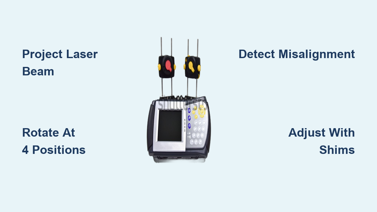
The system achieves this by projecting a laser beam from the fixed shaft to a digital sensor on the opposing shaft. As both shafts rotate together, the sensor tracks the laser position at multiple angles. Any movement in the laser spot reveals misalignment.
Why Shaft Rotation Matters
Shafts are rotated through 0°, 90°, 180°, and 270° to capture full-circle data. This eliminates errors from shaft runout, coupling backlash, and bracket sag.
The system uses trigonometric algorithms to analyze positional changes and calculate offset misalignment, angular misalignment, and required correction at machine feet.
Key Components of Laser Alignment Systems
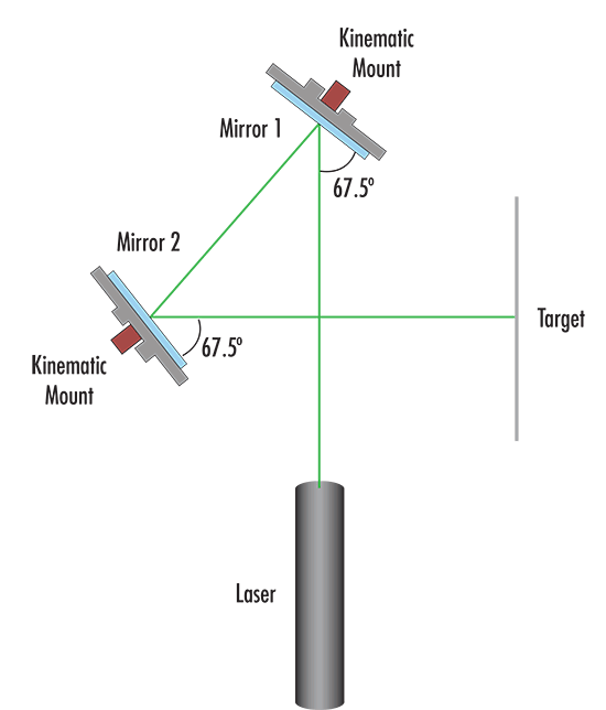
A laser alignment setup is an integrated metrology system with several essential parts.
Laser Emitter and Sensor
The laser emitter sends a focused, modulated beam to a position-sensitive sensor. Modern sensors use CCD or CMOS arrays to detect beam position with 1 µm resolution. Modulated lasers resist interference from ambient light, ensuring accuracy even in bright industrial environments.
Mounting Brackets
Brackets attach to shafts or coupling hubs via magnetic or mechanical clamps. They must be rigid, sag-resistant, and securely fastened. Poor bracket design or long overhangs introduce measurement errors, especially in horizontal planes.
Display and Software Interface
Most systems connect to a tablet or handheld display that shows real-time alignment values, visualizes misalignment graphically, calculates correction values, and stores historical records. Advanced platforms from Fluke, Pruftechnik, and Easy-Laser offer animated correction guides and thermal growth compensation.
Single vs. Dual Laser Systems

Not all laser alignment tools work the same way. Understanding the differences helps you choose the right system.
Single Laser Setup
One side emits while the other detects. As you rotate both shafts, the system measures laser spot displacement, angular and offset values, and foot correction needs. This is the most common configuration for standard motor-pump alignments.
Advantages include:
– Cost-effective solution
– Simple setup process
– Proven accuracy for most applications
Disadvantages include:
– Sensitive to bracket sag
– Requires precise bracket alignment
Dual Laser System
Both units emit and receive lasers simultaneously. This allows real-time bidirectional measurement and instant feedback during adjustment.
Advantages include:
– Compensates for thermal drift
– Reduces setup time
– Detects coupling strain in real time
Disadvantages include:
– Higher initial cost
– More complex calibration requirements
Pro Tip: Use dual-laser systems when aligning equipment with known thermal growth or pipe strain.
Step-by-Step Laser Alignment Process
Follow these 10 steps for accurate, repeatable results.
1. Safety and Machine Preparation
Start with Lockout/Tagout (LOTO) to prevent accidental startup. Clean shafts, couplings, and baseplates. Inspect for worn bearings or damaged couplings. Check foundation bolts for tightness. Identify soft foot by loosening each foot and measuring gap with feeler gauges.
2. Mount Laser and Sensor Units
Attach brackets to both the stationary machine and movable machine. Install the laser on one shaft and the sensor on the other. Ensure brackets are tight and aligned. Avoid long extensions that may sag under gravity.
Warning: Bracket sag causes false offset readings, especially in horizontal alignment.
3. Input Machine Dimensions
Enter key measurements into the software including distance from coupling center to front foot, distance between front and back feet, shaft spacing, and machine RPM for tolerance calculation. Accurate input ensures correct foot correction values.
4. Perform Rotational Measurement
Rotate both shafts together through four positions: 0° at top, 90° at right, 180° at bottom, and 270° at left. Pause briefly at each point for the system to record laser position. Some systems support continuous rotation, capturing hundreds of data points for better noise filtering.
5. Analyze Misalignment Data
The display shows vertical misalignment, horizontal misalignment, and angular deviation. Example output shows front foot needs shimming, back foot needs shimming, and horizontal movement required.
6. Correct Vertical Misalignment
Loosen motor mounting bolts. Add precision steel shims under feet as indicated. Use 0.05 mm, 0.10 mm, or 0.20 mm shims. Never use washers or improvised materials. Tighten bolts in a criss-cross pattern to avoid frame distortion.
Critical: Re-check alignment after tightening because torque can shift position, especially with soft foot.
7. Adjust Horizontal Alignment
Use jacking bolts or pry bars to shift the motor left or right. Make small, incremental moves while watching live feedback. Once aligned, tighten foundation bolts evenly and confirm final position has not shifted.
8. Verify Final Alignment
Re-measure alignment after all corrections. Ensure values are within acceptable tolerance for your machine RPM. If out of spec, repeat adjustments. Always perform a final check with bolts fully torqued.
9. Document the Results
Save a digital report including before and after alignment values, shim changes, machine ID and operator, and cold vs. hot alignment status. Export to PDF or cloud storage for predictive maintenance tracking.
10. Restart and Monitor
Remove LOTO and restart the machine. Monitor for vibration spikes, unusual noise, and temperature rise. Conduct a post-alignment vibration analysis to confirm success. A well-aligned machine typically shows 40–80% lower vibration.
Types of Misalignment Detected

Laser systems identify five key alignment issues.
Offset Misalignment
Shafts are parallel but displaced vertically or horizontally. Symptoms include high radial vibration and premature bearing wear. Fix by shimming vertically or lateral shifting horizontally.
Angular Misalignment
Shafts form an angle at the coupling. Measured in mm/m or mils/inch. Symptoms include high axial vibration and coupling overheating. Fix by differential shimming at front and back feet.
Combination Misalignment
Most common in real-world scenarios. Both offset and angular errors exist. Laser systems calculate combined correction for both planes.
Soft Foot Detection
One or more machine feet do not sit flat on the base. Causes include frame distortion, bolt-induced stress, and uneven baseplate. Fix by shimming individual feet until all sit flush.
Thermal Growth Compensation
Machines expand at different rates when hot. Advanced systems allow input of thermal growth values to pre-compensate, ensuring optimal running alignment.
Accuracy Factors and Error Sources
Even high-precision systems deliver bad data if not used correctly.
Environmental Challenges
Air turbulence refracts the laser beam. Dust or moisture scatters light. Ambient light interferes with sensor. Vibrations from nearby equipment affect measurements. Shield the laser path and measure during low-activity periods.
Mechanical Errors
Bracket sag causes measurement errors. Loose clamps cause drift. Shaft runout creates false readings. Coupling backlash causes inconsistent readings.
Best Practice: Perform a repeatability test. Measure twice. If values differ by more than 0.01 mm, investigate the cause.
Alignment Tolerances by Machine Speed
Alignment standards depend on RPM and criticality.
| RPM Range | Offset Tolerance | Angular Tolerance |
|---|---|---|
| 1,500–3,000 | ≤ ±0.05 mm | ≤ 0.1 mm/m |
| >10,000 (turbines) | ≤ ±0.02 mm | ≤ 0.05 mm/m |
| Low-speed pumps | ≤ ±0.10 mm | ≤ 0.2 mm/m |
Always follow OEM specifications when available.
Laser vs. Traditional Alignment Methods
Laser alignment outperforms older techniques in every way.
Why Dial Indicators Fall Short
Dial indicators are prone to bracket sag. They require complex rim-and-face calculations. They measure one plane at a time with no data logging. They are hard to use in tight spaces.
Why Laser Wins
Laser alignment is faster, achieving in minutes what takes hours with dial indicators. It is more accurate, delivering ±0.01 mm versus ±0.05 mm. Software walks you through the process. It detects soft foot, impossible with dial indicators. It stores complete digital records.
Laser systems eliminate parallax error, mechanical hysteresis, and manual math mistakes. They are now the industry standard for critical machinery.
Industrial Applications
Laser alignment is used wherever reliability matters.
Key Industries
Oil and gas facilities use compressors, pumps, and offshore platforms. Power plants rely on turbines, generators, and feedwater pumps. Water treatment plants operate centrifugal pumps and blowers. Manufacturing facilities run CNC spindles, conveyors, and presses. Marine applications align engine-to-propeller shafts. HVAC systems use chillers and cooling tower fans.
Common Use Cases
New equipment installation requires precise alignment. Post-repair verification confirms correct reassembly. Vibration troubleshooting identifies root causes. Predictive maintenance establishes baselines. Retrofitting older equipment brings it up to modern standards.
Economic and Operational Benefits
Laser alignment pays for itself quickly.
Measurable ROI
Alignment completes 50–70% faster than dial indicators. Vibration reduces by 40–80%. Bearing life extends 3–5 times longer. Energy savings reach up to 10%. Payback period is typically 6–12 months.
Long-Term Advantages
Fewer unplanned outages occur. Maintenance costs decrease. Coupling and seal life extends. Lubricant contamination reduces. Compliance with ISO 10816 and API 670 improves.
Frequently Asked Questions About Laser Shaft Alignment
What is the basic principle behind laser shaft alignment?
Laser shaft alignment projects a laser beam from one shaft to a digital sensor on the opposing shaft. As both shafts rotate together, the sensor tracks laser position at multiple angles. Any deviation reveals misalignment, which the system calculates using trigonometric algorithms to determine angular and offset values.
How accurate is laser shaft alignment compared to dial indicators?
Laser alignment achieves accuracy of ±0.01 mm or better, while dial indicators typically achieve ±0.05 mm. Laser systems eliminate human error, bracket sag, parallax errors, and manual calculation mistakes that plague traditional methods.
What types of misalignment can laser systems detect?
Laser systems detect offset or parallel misalignment, angular misalignment where shafts form an angle at the coupling, combination misalignment containing both types, soft foot where machine feet do not sit flat, and thermal growth misalignment that occurs during operation.
How long does a typical laser alignment procedure take?
A complete laser alignment procedure takes 30-60 minutes for standard motor-pump setups. This represents a 50-70% time savings compared to traditional dial indicator methods that can take several hours for complex alignments.
Do flexible couplings compensate for misalignment?
No. Flexible couplings are designed to absorb minor dynamic shifts and thermal growth, not gross misalignment. Relying on coupling flexibility to compensate for poor alignment leads to premature coupling failure, increased vibration, and reduced bearing life.
Key Takeaways for Laser Shaft Alignment Success
Laser shaft alignment is a precision maintenance technique that projects a laser beam from one shaft to a digital sensor on another, measuring angular and offset misalignments with sub-millimeter accuracy. The process involves systematic steps: preparation with proper lockout/tagout, mounting brackets and sensors, performing rotational measurements at multiple angles, analyzing misalignment data, making vertical corrections with precision shims and horizontal adjustments with jacking bolts, verifying final alignment, and documenting results for future reference. Modern laser systems offer advanced features including wireless connectivity, cloud reporting, multi-machine alignment capabilities, and thermal growth compensation, making them indispensable tools for predictive maintenance programs. By ensuring rotational centerlines are coaxial, laser alignment reduces vibration by 40-80%, extends bearing life by 3-5 times, delivers energy savings up to 10%, and typically pays for itself within 6-12 months through reduced downtime and maintenance costs.