How to Use a Fiber Laser: Quick Guide
If you’re wondering how to use a fiber laser for precision metal marking, you need to understand that success starts before you ever fire the first pulse. Whether you’re engraving stainless steel, anodized aluminum, or titanium, mastering your fiber laser system requires proper lens installation, software configuration, and laser parameter calibration. This guide walks you through every step from initial setup to advanced engraving techniques, so you can produce clean, repeatable marks with confidence.
Using a fiber laser effectively begins with knowing your material, defining your marking goals, and configuring your software for accuracy. You’ll learn how to focus the beam correctly, calibrate your workspace, set optimal speed and power, and avoid common mistakes that degrade quality or damage equipment. By the end, you’ll have a complete workflow that ensures precision, repeatability, and professional-grade output.
Install and Align the Focusing Lens Properly

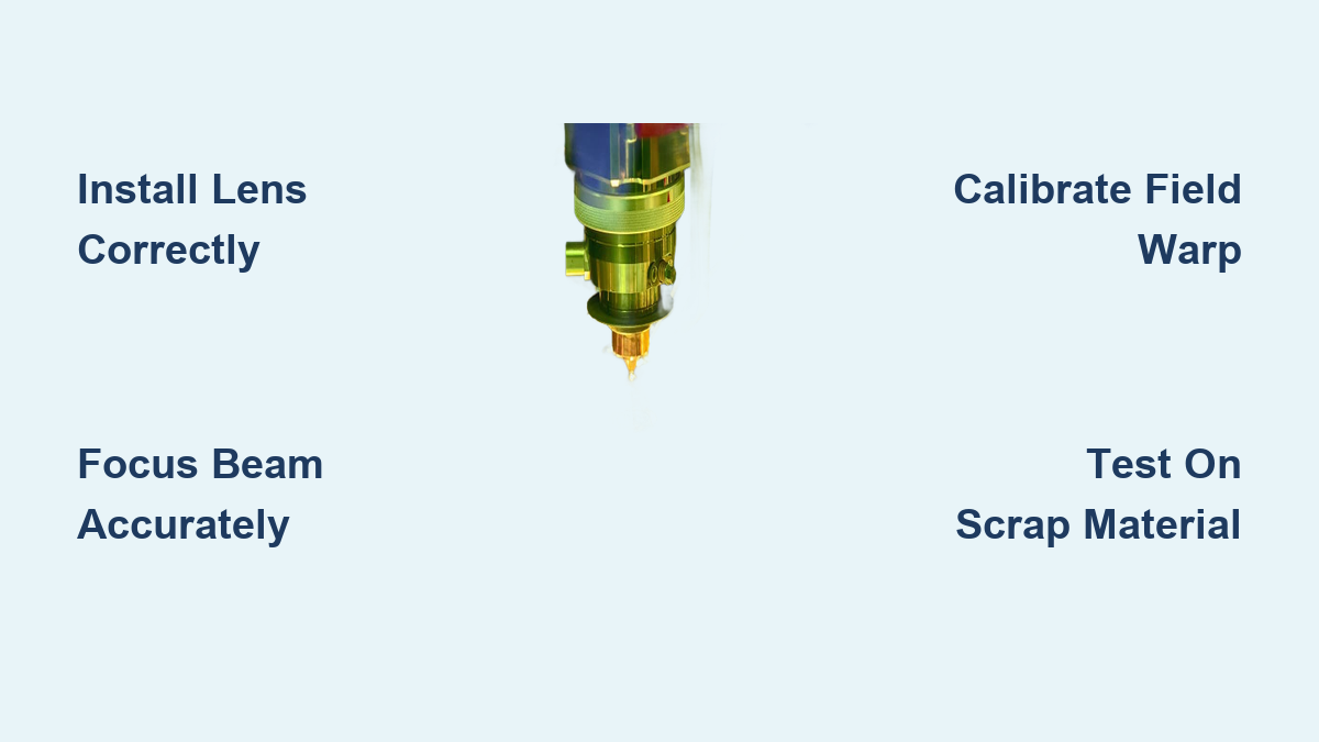
Proper lens installation ensures optimal beam focus and marking precision. A misaligned or improperly seated lens can cause beam distortion, inconsistent depth, or complete marking failure.
Prevent Cross-Threading During Installation
Always avoid cross-threading when installing a new lens. Start by raising the laser head to its highest position. Hold the lens housing steady with one hand while unscrewing the old lens with the other. Never remove the spacer unless absolutely necessary since it protects internal threads. Once removed, cap the old lens and store it safely.
For the new lens, follow these steps:
• Remove protective caps from the lens
• Align the lens carefully with the spacer
• Gently lower it until contact, then rotate counterclockwise slightly until you hear a click indicating thread alignment
• Only then screw it in clockwise until snug
Choose the Right Focal Length for Your Application
Focal length determines working distance and spot size. Common options include 160 mm, 182 mm, 254 mm, and 330 mm. Longer focal lengths allow deeper working distances but produce slightly larger spot sizes, reducing engraving precision. Match your focal length to your application:
• 160–182 mm is best for fine detail and deep engraving
• 254–330 mm is ideal for taller parts or fixtures
Store spare lenses in protective cases and clean only with lens paper and isopropyl alcohol.
Configure EzCad Software for Your Fiber Laser
EzCad2 and EzCad3 are the most widely used software platforms for fiber lasers. Correct setup ensures accurate mark placement, proper scaling, and reliable parameter storage.
Duplicate and Rename EzCad Folders for Each Lens
When switching lenses, duplicate your existing EzCad folder and rename it to reflect the new configuration. For example, rename a folder to ezcad220 for a 220 mm field. Inside the folder, rename the executable from easycad2110f182 to easycad2220f330 for a 220×220 mm field and 330 mm focal length. Create a desktop shortcut and remove hyphens from the name to prevent software errors.
Set Workspace and Display Options Correctly
Open EzCad and configure the workspace with these settings:
• Set units to millimeters for precision
• Set grid spacing to 2 mm for visual alignment
• Enable Show Workspace and select square shape
• Turn on Show Center Cross Line for reference
• Enter field size matching your lens working area (e.g., 220 mm)
• Set bottom-left coordinate to (-110, -110) to center a 220×220 mm field
Adjust Movement and Rotation Settings
Fine-tune navigation settings to speed up design alignment:
• Set nudge distance to 0.1 mm for fine adjustments
• Set big nudge scale to 5 for Shift + Arrow key movement
• Set rotate angle to 15° increments for Ctrl + Arrow keys
These settings improve workflow efficiency during job preparation.
Calibrate Laser Parameters in EzCad

Accurate parameter settings determine mark quality, contrast, and depth. Misconfigured frequency or power can damage the laser or fail to mark the material.
Select Fiber Laser Mode and Set Frequency Limits
In the Laser Control tab, choose Fiber as the laser type. Set maximum and minimum frequencies based on your laser:
• 20W lasers: Set minimum to approximately 20 kHz
• 50W MOPA lasers: Set minimum to 50–80 kHz (internally restricted)
Never operate below the minimum frequency since this risks exceeding 1 mJ per pulse, which can damage internal components.
Enable Key Marking Features
In Machine Behavior, enable these helpful settings:
• Show Start Mark Dialog for confirmation before marking
• Auto Reset Mark Count to reset counter after each job
• Disable Mark When Reach Total Count to prevent over-marking
• Enable Marking Pause Mode to allow pausing with the Esc key
These settings improve control and prevent errors in batch production.
Align the Red Light Pointer with the Laser Path
The red dot must match the actual laser path for accurate positioning. Enable Show Contour and Always Show. Project a 10 mm × 10 mm square with F1. Adjust scale until the red outline matches a physical ruler. This alignment is critical for accurate positioning, especially in multi-part fixtures.
Focus the Laser Beam Accurately
Precise focus maximizes energy density and ensures clean, deep marks. An out-of-focus beam spreads energy, reducing contrast and penetration.
Find the Focal Point by Sound and Light
Follow this step-by-step procedure:
1. Raise the laser head fully and place scrap metal under the lens to protect the bed
2. In EzCad, draw a 20 mm × 20 mm square, center it, and apply hatch fill
3. Set parameters: Speed 1000 mm/s, Power 80%, Frequency 25 kHz
4. Press F1 to preview with red light
5. Wear laser safety goggles rated for 1064 nm
6. Press F2 to fire the laser
7. Slowly lower the head while watching and listening
8. The brightest spark and loudest pop indicate optimal focus
9. Fine-tune within ±0.5 mm for best results
Measure True Focal Distance
Use a metric ruler to measure focal distance accurately:
• Align the ruler vertically with the lens housing
• Measure from the lip of the lens to the ruler’s zero point
• If zero is offset, measure the gap with calipers
• Calculate true focal distance by adding the offset to the ruler reading
For example, if the ruler shows 350 mm and the offset is 6 mm, your true focal distance is 356 mm.
Create a Focal Guide for Repeat Use
Create a focal stick by cutting a wooden or plastic stick to your exact focal length (e.g., 356 mm) with a T-end for quick placement. Alternatively, record the Z-axis bed position when focused. For 1 mm thick material, set bed to focused position plus 1 mm. This eliminates repeated focusing and ensures consistency across jobs.
Calibrate Field Warp for Accuracy
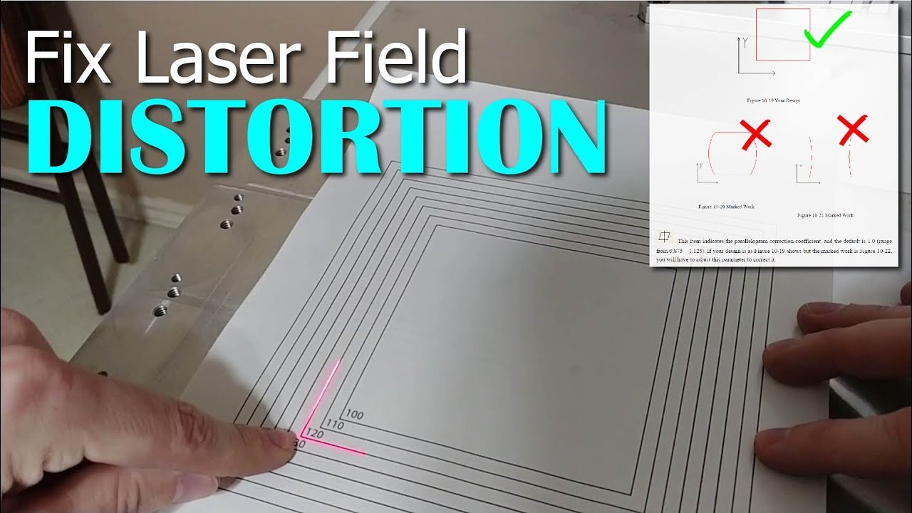
Galvo mirrors can cause optical distortion where corners may stretch or compress. Field warp correction ensures marks are geometrically accurate across the entire workspace.
Use a Post-it Note as Calibration Tool
Place a 76.55 mm × 76.55 mm Post-it note on the worktable. In EzCad, draw a square of the same size and center it. Press F1 to project the red outline. Adjust warp settings until the red lines perfectly align with the Post-it edges.
Apply Warp Corrections for Common Distortions
Use these settings to fix specific distortion types:
• Concave/Convex (X/Y) corrects inward or outward bowing
• Parallelogram (X/Y) fixes skewed or slanted lines
• Trapezoidal (X/Y) adjusts width taper, narrow at one end
Start with scale adjustments to align corners, then make micro-corrections. Save a screenshot of final settings since reinstalling software will erase them.
Optimize Speed, Power, and Frequency Settings

These three parameters control every aspect of the mark. Mastering their balance is key to achieving desired results without trial-and-error.
Set Speed Based on Material and Depth
Speed refers to the laser travel rate measured in mm/s or in/s. Higher speed produces lighter marks and faster processing. Lower speed achieves deeper engraving but risks overheating. Examples include:
• Light anodize removal: 30–35 in/s (approximately 760–890 mm/s)
• Deep metal engraving: 5–10 in/s (approximately 127–254 mm/s), often requiring multiple passes
Match Power to Laser Wattage
Power is the output measured in watts. The software sets a percentage, but actual output cannot exceed hardware limits. Higher power enables faster processing, deeper engraving, and better contrast on hard metals. Always start at 50–70% power and adjust upward as needed.
Tune Pulse Frequency for Material Response
Frequency measured in kHz indicates pulses per second. Lower frequency produces higher energy per pulse for deeper marks, but too low risks laser damage. General guidelines:
• 20W fiber lasers: 20–50 kHz safe range
• 50W MOPA lasers: 50–80 kHz minimum
• MOPA lasers allow low-frequency marking without damage
For black annealing on stainless steel, try 20–30 kHz. For clean ablation, use 100–200 kHz.
Test Marks on Scrap Material Before Production
Never engrave a final part without testing. Use scrap metal to validate settings and avoid costly mistakes.
Create a Test Grid
Design a 4×4 grid in EzCad varying speed across rows and power across columns while keeping frequency constant. Mark on scrap stainless or aluminum. After engraving, inspect which cell has best contrast, any burning or melting, and whether depth is consistent. Save winning settings as a template.
Adjust for Material Type
Different metals respond uniquely to laser parameters:
• Stainless steel: Use lower frequency (20–50 kHz) for black marks
• Anodized aluminum: High speed (800–1000 mm/s), low power (20–30%) to remove coating
• Titanium: Medium power (40–60%), 50–100 kHz for color marking
Always test when switching materials to achieve optimal results.
Use LightBurn for Advanced Engraving
LightBurn is gaining popularity for fiber lasers, especially with newer models. It offers intuitive design tools and advanced features.
Import EzCad Settings into LightBurn
Convert existing EzCad configurations by exporting parameter sets and importing them into LightBurn as custom profiles. Map power, speed, and frequency to layers. This preserves proven settings while using a modern interface.
Engrave Photos and Grayscale Images
To engrave photographs:
1. Import a high-contrast image at 300–600 DPI
2. Apply dithering or halftone pattern
3. Map grayscale to power where black equals 100% and white equals 0%
4. Use variable power mode for smooth tonal transitions
Test on aluminum or coated steel for best photo results.
Create 3D Engravings with Height Maps
Use grayscale images as height maps where darker pixels indicate deeper engraving. Control depth via power modulation or multiple passes. This technique is ideal for medallions, coins, and nameplates. In LightBurn, assign power curves to brightness levels for precise depth control.
Set Up Rotary Engraving for Cylinders
Engrave pens, bottles, or gun barrels using a rotary axis for cylindrical objects.
Install and Configure the Rotary Axis
Mount the rotary table on the worktable and connect to the laser controller via external port. In software (EzCad or LightBurn), enable rotary mode and enter object diameter to ensure correct scaling. A 10 mm diameter rod requires different scaling than a 30 mm cylinder.
Align and Test Before Production
Clamp the object securely and use red light preview to position the start point. Run a test line around the circumference and check for stretching (incorrect diameter) or misalignment (fixture wobble). Adjust until the mark is uniform and continuous.
Maintain Safety and Equipment
Fiber lasers are powerful tools and safe operation protects you while extending machine life.
Wear Proper Laser Safety Gear
Always wear laser safety goggles rated for 1064 nm wavelength. Never look into the beam path, even when the laser is off. Use an enclosure or interlock if available on your system.
Ensure Fume Extraction
Metal marking produces hazardous particulates. Use a fume extractor with HEPA and carbon filters. Position the intake close to the marking area and clean filters regularly to maintain effectiveness.
Perform Routine Maintenance
Clean these components weekly:
• Lens using lens paper and isopropyl alcohol
• Protective window to remove dust and spatter
• Mirrors if accessible, inspecting for damage
Store lenses capped and in protective cases when not in use.
Frequently Asked Questions About Using a Fiber Laser
What is the best frequency for marking stainless steel black?
For black annealing on stainless steel, use 20–30 kHz frequency. Lower frequencies produce higher energy per pulse, creating the dark oxide layer without ablating the surface.
How do I know if my fiber laser is properly focused?
Fire the laser while slowly raising or lowering the head. The point of maximum brightness and loudest sound indicates optimal focus. Fine-tune within ±0.5 mm for best results.
Can I use LightBurn with my EzCad fiber laser?
Yes, LightBurn can import EzCad configurations. Export your parameter sets from EzCad and import them into LightBurn as custom profiles to preserve your proven settings.
What power setting should I start with?
Always start at 50–70% power and adjust upward as needed. Starting conservative prevents material damage and allows you to find the optimal setting through testing.
How do I correct distorted marks at the edges of my workspace?
Use field warp calibration in EzCad. Place a 76.55 mm × 76.55 mm Post-it note, draw a matching square, and adjust warp settings (concave/convex, parallelogram, trapezoidal) until the red outline aligns perfectly.
Do I need a rotary axis for cylindrical engraving?
Yes, a rotary axis is required for cylindrical objects. Configure it in your software by entering the object diameter to ensure correct scaling across curved surfaces.
Key Takeaways for Using a Fiber Laser Effectively
Using a fiber laser effectively combines technical setup, parameter knowledge, and hands-on practice. Start with proper lens installation, configure your software accurately, focus the beam precisely, and calibrate for distortion before attempting production marks. Always test settings on scrap material before working on final pieces to avoid costly mistakes.
Use EzCad or LightBurn to control speed, power, and frequency, adjusting for material type and desired effect. Lower frequencies work better for black annealing on stainless steel while higher speeds suit light anodize removal. Apply advanced techniques like rotary and 3D engraving only after mastering the basics.
Stay safe with proper goggles rated for 1064 nm and maintain fume extraction to protect your health. Join the Fiber Laser Metal Engraving Facebook community to continue learning from experts and troubleshoot issues as they arise. With this comprehensive workflow, you’re equipped to produce professional, repeatable results every time.