How to Use a Laser Diode: Quick Steps
Laser diodes are powerful semiconductor devices that generate coherent light for applications ranging from consumer electronics to industrial systems. Unlike regular LEDs, laser diodes are current-driven devices that require precise current regulation to operate safely. Connecting a bare laser diode directly to a battery or microcontroller pin without proper current limiting often results in instant destruction due to thermal runaway.
This guide walks you through exactly how to use a laser diode safely and effectively, whether you are a hobbyist building your first project or an engineer designing a high-power system. You will learn how to choose the right driver, set up proper thermal management, modulate output, and avoid common pitfalls that destroy diodes.
Why Laser Diodes Require Current Control
Laser diodes have a negative temperature coefficient, meaning their electrical resistance decreases as temperature rises. This creates a dangerous thermal runaway cycle where increased temperature causes higher current draw, which generates more heat, leading to catastrophic failure in seconds. Unlike LEDs or incandescent bulbs that tolerate voltage variations, laser diodes demand constant current regulation.
The actual voltage across a laser diode self-regulates to its forward voltage drop, typically between 1.8 and 3.5 volts depending on wavelength and material. The critical parameter is current, not voltage. Even high-voltage sources can drive a laser diode safely if current is strictly limited.
Never connect a bare laser diode directly to an Arduino 5V pin, USB power, or a battery without a current-regulated driver. This is the most common mistake that destroys laser diodes instantly.
Choosing Your Laser Setup
Using a Pre-Built Module (Beginner-Friendly)
For most users, especially those new to laser electronics, the safest approach is using a pre-built laser module such as the KY-008 or similar 5V red laser. These modules integrate the diode, driver, optics, and housing into one compact unit that operates safely with direct power.
These modules offer several advantages for beginners. They operate on 3.3V to 12V DC, turn on immediately when powered, and often include TTL input for digital control. You can connect them directly to Arduino, Raspberry Pi, or USB power without additional circuitry.
Wiring is straightforward. Connect the red wire to V+ and the black wire to GND. If your module has a yellow or white wire, connect it to a microcontroller pin for on/off control. Use an N-channel MOSFET or transistor to switch the ground path for better isolation and control.
Avoid applying PWM directly to the power rail unless the module specifically supports analog modulation, as peak currents can damage the internal diode.
Driving a Bare Diode Directly (Advanced)
For advanced applications requiring specific power levels or custom integration, you must use a constant current driver. A bare laser diode must never be connected directly to any voltage source, including batteries, power supplies, or microcontroller pins.
The reason is simple: without current regulation, any small voltage change above the forward threshold causes exponential current rise. Even momentary voltage spikes destroy the diode permanently.
Always use a constant current driver specifically designed for laser diodes to prevent thermal runaway and ensure stable operation.
Building a Constant Current Driver Circuit
Using an LM317 as a Current Regulator
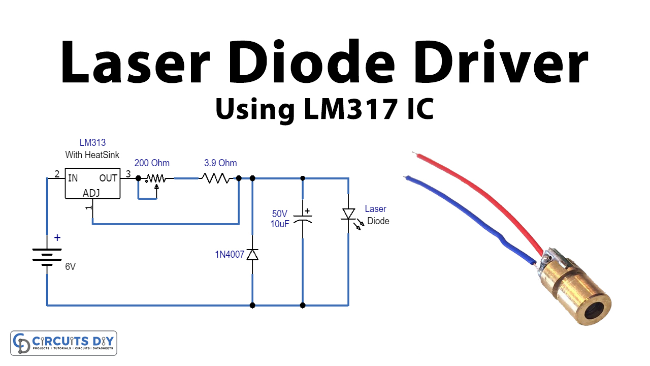
The LM317 voltage regulator can be configured as a precision constant current source, making it ideal for low to medium-power laser diodes. This approach provides reliable performance without complex circuitry.
The circuit configuration requires connecting Vin to the LM317 input pin, then a resistor (R_set) from the output to the adjustment pin. The laser diode connects positive to the output and negative to the adjustment pin, with the circuit completed to ground.
The output current follows this formula: I = 1.25 / R_set, where 1.25V is the reference voltage between the output and adjustment pins. For 12mA operation, calculate R_set = 1.25 / 0.012, which equals approximately 104 ohms. Use a standard 100-ohm resistor for practical applications.
Add a 100-ohm potentiometer in parallel with R_set for adjustable current control. The power input must be at least 3 volts higher than the diode forward voltage for stable regulation. Place a multimeter in series (set to mA) during testing to verify actual current before connecting the diode permanently.
Powering High-Output Diodes Safely
Selecting the Correct Driver Type
Different power levels and applications require different driver architectures. Understanding the trade-offs helps you choose the right driver for your project.
Linear drivers like the LM317 offer low noise and smooth output, making them suitable for analog modulation and lab setups. The downside is inefficiency, as they dissipate excess power as heat. They work best for systems under 1 watt.
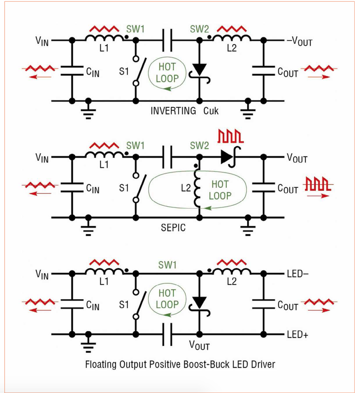
Switching drivers (buck or boost) offer up to 90% efficiency with minimal heat generation. Use a buck (step-down) driver when your input voltage exceeds the diode forward voltage, such as powering a 2.5V red diode from a 5V supply. Use a boost (step-up) driver when input voltage is lower than the diode requirements, such as driving a 4.5V blue diode from 3.3V or USB.
Switching drivers can generate electrical noise and should never be tested unloaded, as output voltage can spike dangerously. To identify driver type, connect two blue LEDs (about 3.3V each) in series to the driver output. If they light from a 4V input, you have a boost driver.
Calibrating Laser Current Properly
Following Safe Setup Procedures
Improper calibration is a leading cause of laser diode failure. Follow this step-by-step procedure to set up your diode safely.
First, consult the datasheet to find the maximum current (Imax), threshold current (Ith), and forward voltage (Vf). Second, ensure your input voltage provides adequate headroom, typically Vf plus 3 volts for LM317-based circuits. Third, discharge any capacitors by shorting output terminals before powering on to prevent surge damage.
Next, insert a multimeter in series between the driver and diode cathode. Set it to DC current in the mA or A range. Power on gradually and adjust the potentiometer slowly while watching the current display. Finally, stay below the maximum rating, operating at 70 to 80% of Imax for longer diode life.
Never exceed rated current, even briefly. Overdriving causes catastrophic optical damage (COD) that permanently destroys the diode.
Controlling Laser Output with Modulation
Applying TTL or Analog Modulation
Laser diodes support modulation for communication, sensing, pulsing, and visual effects. Understanding the modulation types helps you choose the right approach for your application.
TTL (digital) modulation uses 0V for off and 5V for on, making it ideal for laser shows, encoders, and tripwire circuits. Many modules accept direct logic-level signals without additional components.
Analog modulation uses 0 to 5V input for proportional brightness, enabling smooth dimming. This requires a driver with analog input capability and works well for scientific instruments and color-mixing applications.
Never apply PWM directly to the power rail of a bare diode, as this causes dangerous current spikes. Instead, use the modulation input built into your driver or module.
Adding PWM Control to Any Driver
Use an N-channel MOSFET to switch the driver ground path for PWM control. Connect the gate to your PWM signal source (such as an Arduino), the source to ground, and the drain to the negative terminal of the laser driver. Add a 10k-ohm pull-down resistor from the gate to ground to ensure proper off-state behavior.
Recommended PWM frequency ranges from 60 to 255 Hz. Avoid very low duty cycles below 10%, as these can cause current spikes that damage the diode.
Managing Heat Effectively
Mounting Diodes on Heatsinks
Heat is the enemy of laser diode longevity. Even 100mW diodes benefit significantly from proper heatsinking, and higher-power units require it for any meaningful operating life.
Use a heatsink whenever power exceeds 100mW, during continuous wave (CW) operation, or when ambient temperature exceeds 25°C. Apply thermal paste or a thermal pad between the diode package and heatsink for optimal heat transfer. Secure the assembly with an appropriate housing such as a 12mm module bracket, and avoid blocking airflow in enclosed spaces.
High-power diodes exceeding 1W may require active cooling through fans or thermoelectric coolers (TEC). Monitor temperatures during operation and add cooling capacity if the diode case exceeds 50°C.
Using 3-Pin Laser Diodes with Feedback
Implementing Closed-Loop Control
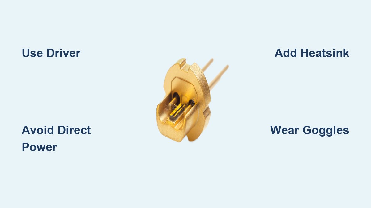
Many laser diodes, particularly those salvaged from DVD burners, have three pins instead of two. These include a monitor photodiode that detects light emitted from the rear facet of the laser cavity.
The three pins serve specific functions. Pin 1 is the anode (laser diode positive), Pin 2 is the common ground, and Pin 3 is the photodiode cathode providing a current proportional to laser output power.
To implement feedback control, connect the photodiode to a transimpedance amplifier built from an op-amp and feedback resistor. The amplifier output controls a transistor that regulates laser current, adjusting in real time to maintain constant output despite temperature changes or aging.
This feedback approach is essential for fiber optics, medical devices, and precision instruments requiring stable optical power.
Matching Wavelength to Your Application
Choosing Diode by Material and Color
Laser wavelength determines its use case and optical requirements. Different materials produce different wavelengths, each suited to specific applications.
Violet diodes at 405nm serve Blu-ray drives, fluorescence excitation, and UV curing. Blue diodes from 450 to 480nm power projection, engraving, and underwater communications. Green diodes at 520nm appear in laser shows, alignment tools, and pointers. Red diodes from 635 to 670nm are common in scanners, holography, and alignment applications.
Infrared diodes at 780 to 850nm serve CD and DVD drives, printing, and LIDAR systems. The 980nm wavelength powers fiber pumping and medical applications. Longer wavelengths at 1310 and 1550nm are standard in telecom and sensing.
Infrared lasers are invisible but still dangerous. Always use beam detectors and safety goggles when working with IR wavelengths.
Essential Laser Safety Protocols
Following Laser Safety Standards
Laser diodes can cause permanent eye damage, even from reflected beams. Following proper safety protocols protects your vision and the vision of others around you.
Laser hazard classification follows IEC 60825-1 standards. Class 1 diodes under 0.39mW are safe under all conditions. Class 2 diodes under 1mW rely on the blink reflex for protection. Class 3R diodes from 1 to 5mW carry some risk if stared at directly. Class 3B diodes from 5 to 500mW are eye hazards from direct and reflected exposure. Class 4 diodes above 500mW cause skin burns and fire hazards.
Critical safety steps include wearing wavelength-matched laser goggles, never pointing at people or animals, using beam stops and enclosures, labeling work areas with warning signs, avoiding reflective surfaces in the beam path, and using interlocks on enclosed systems.
The golden rule: never look into the beam or point it at anyone else’s eyes.
Selecting the Right Package Type
Matching Housing to Power and Use Case
Different packages offer varying thermal, optical, and electrical characteristics. Choosing the right package ensures proper performance and integration.
TO-56 or TO-18 packages handle up to about 500mW and appear in pointers and optical readers. C-mount packages support 1 to 15W for industrial and custom optics applications. Butterfly packages accommodate several watts with integrated thermoelectric coolers and monitor photodiodes, making them standard for telecom and precision systems.
Diode bars handle tens to thousands of watts for welding and cutting applications but require active cooling. VCSEL arrays serve custom applications like face recognition and sensors.
C-mount diodes require careful mounting and lens alignment, making them ideal for OEM integration rather than beginner projects.
Troubleshooting Common Problems
Fixing No Light or Weak Output
Several common problems have straightforward solutions. Use this troubleshooting guide to diagnose and fix issues quickly.
If your diode produces no light, check for a dead diode, reversed polarity, or no current flow. Test with a multimeter and verify all connections. Weak or flickering beams usually indicate insufficient current, poor contacts, or a failing driver. Measure the actual current and clean or replace connections as needed.
Overheating results from inadequate heatsinking or excessive drive current. Add a proper heatsink, reduce the operating current, and improve ventilation. Unstable output often stems from lack of feedback control or power fluctuations. Implement a monitor photodiode circuit for closed-loop regulation.
High beam divergence indicates bad or misaligned collimation lenses. Replace with a proper aspheric collimator for better beam quality.
Extending Diode Lifespan
Preventing Premature Failure
Laser diodes can last 10,000 to 50,000 hours when handled correctly. Proper care maximizes your investment and ensures reliable operation.
Operate below maximum rated current, targeting 70 to 80% of Imax for extended life. Always use ESD-safe tools and wear a wrist strap during handling to prevent static damage. Avoid exposure to dust, moisture, and static discharge.
Use soft-start circuits to prevent inrush current spikes that damage diodes. Store unused diodes in anti-static bags in a cool, dry environment.
Catastrophic optical damage (COD) often results from ESD or sudden current spikes. Preventing these conditions ensures your diode performs reliably for years.
Frequently Asked Questions About Using Laser Diodes
Can I Connect a Laser Diode Directly to a Battery?
No, you should never connect a bare laser diode directly to any voltage source, including batteries. Laser diodes require constant current regulation to prevent thermal runaway. Use a pre-built module with built-in driver for simple projects, or add a constant current driver circuit for bare diodes.
What Happens If I Exceed the Maximum Current Rating?
Exceeding maximum current, even briefly, causes catastrophic optical damage (COD) that permanently destroys the laser diode. Always stay below the datasheet ratings, ideally operating at 70 to 80% of maximum for longer life. Use a multimeter in series to verify current during setup.
Can I Use PWM to Control Laser Brightness?
You can use PWM, but never apply it directly to the power rail of a bare diode. Instead, use a driver with built-in modulation input, or add an N-channel MOSFET to switch the ground path. Keep PWM frequency between 60 and 255 Hz and avoid duty cycles below 10% to prevent current spikes.
Do I Need a Heatsink for My Laser Diode?
Yes, for diodes over 100mW, continuous operation, or warm environments, a heatsink is essential. Even lower-power diodes benefit from heatsinking for improved reliability. Use thermal paste between the diode and heatsink for optimal heat transfer.
How Do I Choose the Right Wavelength for My Application?
Choose wavelength based on your application. Red (635-670nm) works for alignment and holography. Blue (450-480nm) suits engraving and projection. Green (520nm) appears in laser shows and pointers. Infrared (780-1550nm) serves telecom, sensing, and CD/DVD applications.
What Safety Gear Do I Need for Laser Diodes?
Wear wavelength-matched laser safety goggles whenever working with lasers above Class 2 power. Class 3B and 4 lasers require additional protections including beam enclosures, warning signs, and interlocks. Never operate high-power lasers without proper eye protection.
Key Takeaways for Using Laser Diodes Successfully
Laser diodes are incredibly useful components, but they demand respect and proper handling to deliver reliable performance. The three most critical factors for success are current regulation, thermal management, and safety awareness.
Always use a constant current driver for bare laser diodes to prevent thermal runaway and instant destruction. Never exceed datasheet ratings, and verify actual current with a multimeter in series during setup. For modules, ensure your power supply matches specifications and avoid PWM unless the module supports it.
For thermal management, mount high-power diodes on heatsinks with thermal interface material. Monitor temperatures during operation and add active cooling for demanding applications. Proper heat handling extends diode life dramatically.
Finally, laser safety is non-negotiable. Wear appropriate goggles, never point lasers at people, use beam stops and enclosures, and label your work area. Infrared lasers are invisible but still dangerous.
With these principles in mind, you are ready to build laser projects with confidence, whether lighting up a simple indicator or designing a precision optical system. Start with modules if you are new to laser electronics, and progress to bare diodes with drivers as you gain experience.