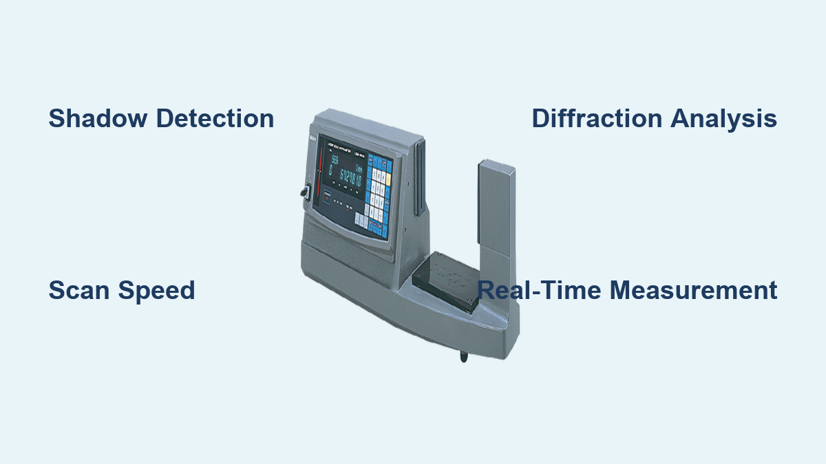
How a Laser Micrometer Works: Quick Guide
Have you ever wondered how manufacturers measure tiny wires, optical fibers, or precision tubing with micron-level accuracy without touching them? The answer lies in the laser micrometer, a non-contact measurement tool that delivers high-speed, repeatable dimensional data using light instead of physical force. Unlike traditional micrometers that squeeze an object between two metal surfaces, laser micrometers use a scanning laser beam and optical detection to determine size by analyzing how long the object blocks the light. This allows for real-time monitoring of fast-moving, hot, or fragile parts in industries like aerospace, medical device manufacturing, and fiber optics.
At its core, a laser micrometer works by measuring the duration of laser beam interruption, a shadow cast by the object, and converting that time into a precise dimension using a simple but powerful formula. Advanced models go even further, using laser diffraction patterns to measure ultra-fine materials down to 5 µm. Whether you’re troubleshooting a production line or selecting a gauge for quality control, understanding how this technology works can help you achieve tighter tolerances, reduce waste, and improve process efficiency.
The Core Principle Behind Laser Micrometer Technology
.jpg)
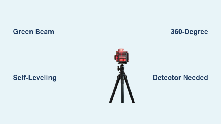
The fundamental mechanism enabling laser micrometers is laser beam scanning combined with time-based shadow detection. When an object passes through a rapidly scanned laser beam, it blocks part of the beam, casting a temporary shadow on a photodetector located opposite the emitter. The duration of this shadow is directly proportional to the dimension of the object in the measurement plane.
The calculation follows a straightforward formula:
Dimension = Scan Speed × Shadow Time
This equation forms the basis of all scanning-type laser micrometers. The scan speed is precisely known and constant, while the shadow time is measured with nanosecond-level precision. Multiplying these values yields the physical dimension, typically outer diameter, width, or thickness of the object at that point. Thousands of such measurements can be taken per second, enabling real-time monitoring and feedback control in high-speed production environments.
An advanced alternative, used in high-end systems like CERSA Laser Diffraction Sensors, relies on optical diffraction rather than mechanical scanning. In this method, a coherent laser beam passes around a thin object, and the resulting interference pattern is captured by a sensor array. The spacing between fringes is inversely proportional to the object’s diameter, and using Fourier transform algorithms, the system calculates the exact diameter from the fringe pattern.
Shadow Detection Using Laser Scanning
The heart of most laser micrometers is shadow-based measurement, where an object passing through a rapidly scanned laser beam creates a temporary blockage. This interruption is detected on the opposite side, and the duration of the shadow is used to calculate physical dimensions like diameter, thickness, or width. Because the laser sweeps at a known speed, the longer the shadow, the larger the object in that plane.
This method enables continuous, non-contact measurements at speeds up to 3,200 scans per second, making it ideal for high-throughput production environments such as wire drawing or plastic extrusion. Since there is no physical contact, delicate components like thin-walled tubing or fine metal filaments are not damaged during inspection.
Laser Beam Sweep Mechanism
To achieve consistent and rapid scanning, laser micrometers use a rotating polygon mirror, a multi-faceted prism spinning at high speed up to 192,000 RPM. As the laser beam reflects off each facet of the mirror, it sweeps across the measurement zone in a straight line, creating a light sheet that passes through any object in its path. The rotation is precisely controlled to maintain constant angular velocity, ensuring uniform scan speed.
This mechanical scanning action allows the system to take thousands of measurements per second, capturing even slight variations along a moving product’s length. Scan rates typically range from 2,000 to 3,200 scans per second, enabling tight axial sampling.
Shadow Time and Dimension Calculation
When the object interrupts the laser beam, the photodetector senses the start and end of the blockage. Electronics measure the pulse width of this shadow with nanosecond precision. Using the fundamental equation, the system calculates the actual size in real time.
For example, if a copper wire blocks the beam for 10 microseconds and the scan speed is 100 m/s, the diameter calculates as 100 m/s multiplied by 10 µs, equaling 1 mm. This calculation happens instantly, enabling immediate feedback for process control systems.
Diffraction-Based Measurement for Ultra-Fine Objects
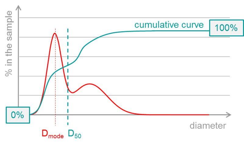
While shadow detection dominates industrial applications, diffraction-based laser micrometers offer superior performance for extremely small or vibrating objects. Instead of relying on a moving mirror, these systems analyze the interference pattern created when laser light bends around a thin object such as a 10 µm medical guidewire.
Interference Fringe Analysis
As coherent laser light passes near a fine object, it diffracts, producing alternating bright and dark bands called diffraction fringes. The spacing between these fringes is inversely proportional to the object’s diameter. A sensor array captures this pattern, and a built-in processor uses Fourier transform algorithms to compute the exact size.
This technique eliminates the need for mechanical scanning, resulting in no moving parts, reduced maintenance, and immunity to vibration, common problems in traditional systems.
Advantages Over Scanning Types
Diffraction-based sensors excel where scanning micrometers struggle. They can measure down to 5 µm with sub-micron repeatability and deliver true instantaneous readings without averaging. These sensors are immune to wire sway or oscillation during measurement, making them ideal for microfibers, optical fibers, and semiconductor wires. Models like the CERSA Laser Diffraction Sensor leverage this principle for applications requiring maximum stability and precision.
Core Components of a Laser Micrometer

Every laser micrometer relies on a set of key components working in harmony to deliver accurate, repeatable results. Understanding these parts helps in selecting, maintaining, and troubleshooting the system.
Laser Source and Beam Quality
Most systems use a semiconductor laser diode emitting visible red 650 nm or infrared 780 to 850 nm light. These lasers are compact, energy-efficient, and long-lasting. The beam must be coherent and collimated, meaning it stays narrow and parallel over distance, to ensure sharp edge detection. Some specialized units still use helium-neon lasers for higher beam quality, though they are bulkier and less durable than diodes.
Rotating Polygon Mirror
This high-speed component deflects the stationary laser beam into a linear sweep. Mounted on a precision motor, the multi-sided mirror rotates continuously, with each face redirecting the beam across the measurement zone. Its reliability directly impacts system lifespan, as bearings can wear over time, requiring periodic servicing.
Collimating and Condensing Optics
Optical lenses shape and direct the beam. The collimating lens keeps the beam parallel, minimizing divergence. The condenser lens focuses the light into a thin ribbon for better edge contrast. These lenses ensure the laser remains focused across the full measurement gap, improving accuracy and signal clarity.
Photoelectric Receiver
Positioned opposite the laser emitter, the photodiode or photodiode array detects when the beam is blocked. It converts optical changes into electrical signals, marking the start and end of the shadow. High temporal resolution allows precise timing, while built-in filters reduce interference from ambient light, shop lighting, or sunlight.
Signal Processing Unit
The brain of the system contains a microprocessor or DSP that measures shadow duration, applies calibration factors, compensates for temperature drift and optical imperfections, and outputs dimension in µm or mm. Advanced models include SPC functions, tolerance checking, and max/min tracking for quality assurance.
Transmitter and Receiver Housing
Typically arranged in a U-shaped or split-body design, the housing maintains alignment between the laser and detector. Industrial versions feature IP65/IP67 ratings, air-purge fittings, and cooling jackets to withstand dust, moisture, and extreme temperatures.
Multi-Axis Configurations for Shape Analysis
While single-axis systems measure one dimension, multi-axis setups provide comprehensive shape profiling, critical for detecting ovality, eccentricity, or flat spots.
Dual-Axis Systems: Measure X and Y Dimensions
Two perpendicular laser pairs scan the object from horizontal and vertical directions. This allows calculation of major and minor diameters, ovality which is out-of-roundness, and eccentricity. By combining both measurements, the system computes a more accurate average diameter and identifies shape deviations that single-axis models might miss.
Triple-Axis Systems: Near-Full Circumference Coverage
With three lasers spaced 60° apart, triple-axis micrometers cover about 90% of the circumference, offering the highest defect detection probability. They detect lobing, asymmetrical deformations, and flat spots or kinks. These systems are preferred in aerospace, medical, and high-precision manufacturing where even minor flaws can compromise performance.
Performance Specifications: Speed, Accuracy, Range
Choosing the right laser micrometer depends on matching performance specs to application needs.
Measurement Speed
Standard units perform 2,000 to 3,200 measurements per second, sufficient for most extrusion and drawing lines. High-end models reach 10,000 Hz, enabling axial sampling as tight as 0.1 mm at high speeds, critical for detecting micro-defects.
Resolution and Accuracy
Typical resolution is 0.1 µm, while high-end resolution reaches down to 0.01 µm which is 10 nm. Accuracy ranges from ±0.1 µm to ±1 µm, depending on calibration. Linearity can be as good as 12 ppm. Laboratory-grade instruments with interferometric correction achieve sub-100 nm reproducibility.
Diameter Measurement Range
Available ranges vary significantly. Entry-level models cover 0.1 mm to 10 mm. Industrial models handle 0.05 mm to 50 mm. Diffraction-based sensors measure 5 µm to 2 mm. Large-bore models reach up to 160 mm or 6.3 inches. Always select a model with a buffer beyond your typical range to maintain accuracy.
Advantages of Non-Contact Laser Measurement
Laser micrometers outperform mechanical gauges in many industrial settings due to their unique benefits.
No Part Damage or Sensor Wear
Since there is no physical contact, soft, hot, or delicate materials like rubber tubing, molten glass, or fine wires are measured safely. There is also no wear on the sensor, extending service life significantly.
Real-Time Monitoring and SPC Integration
With outputs compatible with PLCs, SCADA, and SPC software, laser micrometers feed live data into control systems. This enables immediate die adjustments, automatic rejection of out-of-tolerance parts, and statistical process control dashboards. Operators can track trends and prevent scrap before it occurs.
Automation and Industry 4.0 Readiness
Modern models support Ethernet/IP, USB, RS-232, and Digimatic connections. They include DIN-rail processors for machine integration and cloud-connected analytics for predictive maintenance. They fit seamlessly into smart factories and robotic inspection cells.
Limitations and Practical Considerations
Despite their advantages, laser micrometers have constraints that must be managed.
Mechanical Wear in Scanning Systems
Rotating mirrors and motors are subject to bearing wear and vibration, requiring periodic maintenance. Over time, misalignment can degrade accuracy, making regular checks essential.
Vibration-Induced Errors
In wire measurement, vibrating or swaying parts cause inconsistent shadow times. Scanning systems often average multiple readings, which can mask real-time fluctuations. Diffraction-based sensors avoid this issue entirely.
Environmental Challenges
Dust, oil mist, steam, or temperature swings can interfere with beam transmission. Solutions include air-purge fittings to keep lenses clean, IP67 enclosures for harsh environments, and cooling/heating jackets for thermal stability.
Material and Surface Effects
Transparent materials like clear plastic may require transparent mode or a reflective backdrop. Highly reflective surfaces can scatter light, causing false triggers. Matte black surfaces absorb light well and provide excellent contrast for accurate readings.
Calibration Requirements
Regular calibration using traceable gauge blocks or reference wires is essential. Done every 6 to 12 months, it ensures compliance with standards like NIST or UKAS. Calibration must occur at the correct focal plane and temperature.
Industrial Applications Across Sectors
Laser micrometers play a vital role in quality assurance and process control across numerous industries.
Wire and Cable Manufacturing
Continuous diameter monitoring during drawing ensures ±1 µm tolerance compliance. Feedback loops adjust capstans and dies in real time, minimizing material waste and ensuring electrical performance.
Tube and Pipe Extrusion
Real-time OD, ovality, and wall thickness measurement allows automatic die correction. This is used for plastic, rubber, and metal tubing in automotive and medical applications.
Fiber Optics and Glass Fiber Production
These systems measure preforms and drawn fibers down to single-micron diameters, ensuring optical consistency and tensile strength.
Aerospace and Automotive
This technology inspects fuel lines, brake hoses, turbine blades, and precision shafts where dimensional accuracy impacts safety and performance.
Medical Devices
Laser micrometers are critical for measuring catheters, needles, syringe barrels, and implantable wires under strict FDA and ISO regulations.
Rolling Mills and Metal Processing
They monitor rod and bar diameter during hot or cold rolling, detecting shrinkage, ovality, and surface defects.
Selection Criteria: Choosing the Right Model
To get the best performance, consider these factors when selecting a laser micrometer.
Diameter Range and Part Size
Ensure the model covers your minimum and maximum dimensions with margin. Using a sensor at its limits reduces accuracy significantly.
Scan Rate vs. Line Speed
Higher line speeds require faster scan rates. At 200 m/min, a 0.1 mm axial step needs approximately 3,300 scans per second. Choose 5,000 Hz or higher for tight sampling requirements.
Accuracy and Resolution Needs
Match resolution to your tolerance. A ±5 µm spec does not need 0.01 µm resolution, but a ±0.5 µm requirement certainly does.
Environmental Conditions
For dirty, hot, or humid areas, select IP67-rated housings, air purge, or cooling jackets to ensure reliable operation.
Technology Type
Scanning mirror systems offer lower cost and wide availability but need maintenance. Diffraction-based systems have higher initial cost and no moving parts, making them better for vibration-prone or ultra-fine applications.
Axis Configuration
Single-axis is cost-effective for basic OD checks. Dual-axis detects ovality and eccentricity. Triple-axis provides best full shape profiling and flaw detection.
Maintenance and Long-Term Reliability
Proper care ensures years of accurate service from your laser micrometer.
Routine Maintenance
Clean lenses and windows regularly with approved wipes. Inspect rotating mirror for wear or imbalance. Check alignment after relocation or impact. Lubricate bearings per manufacturer schedule for scanning types.
Calibration Best Practices
Use certified reference standards. Calibrate at operating temperature and distance. Maintain traceability to NIST or equivalent. Schedule calibration every 6 to 12 months depending on usage.
Expected Lifespan
Scanning systems typically last 5 to 10 years with proper maintenance. Solid-state diffraction systems often exceed 10 years due to no moving parts. Typical warranty ranges from 1 to 3 years.
Frequently Asked Questions About Laser Micrometers
What is the basic principle of a laser micrometer?
A laser micrometer works by projecting a rapidly scanning laser beam across a measurement zone and detecting the time duration during which an object blocks the beam. This shadow time is converted into a dimensional measurement using the formula dimension equals scan speed multiplied by shadow time.
What is the difference between scanning and diffraction-based laser micrometers?
Scanning laser micrometers use a rotating polygon mirror to sweep a laser beam across the measurement zone and calculate size from shadow duration. Diffraction-based micrometers analyze interference patterns created when laser light bends around an object, offering higher accuracy for ultra-fine measurements with no moving parts.
What materials can be measured with a laser micrometer?
Laser micrometers work with metals, plastics, rubber, glass fibers, and other opaque or semi-opaque materials. Transparent materials like clear plastic or glass may require special transparent mode settings or reflective backdrops for accurate measurement.
How accurate is a laser micrometer?
Typical accuracy ranges from ±0.1 µm to ±1 µm depending on model and calibration. High-end laboratory-grade instruments achieve resolution down to 0.01 µm or 10 nm with sub-100 nm reproducibility using interferometric enhancements.
What industries use laser micrometers?
Key industries include wire and cable manufacturing, tube and pipe extrusion, fiber optics production, aerospace and automotive component manufacturing, medical device production, and rolling mills. Any industry requiring tight dimensional tolerances benefits from laser micrometer technology.
How often should a laser micrometer be calibrated?
Calibration is recommended every 6 to 12 months depending on usage intensity and quality standards. Calibration must use traceable standards and be performed at the correct focal distance and designated measurement plane.
Key Takeaways for Understanding Laser Micrometers
Laser micrometers combine speed, precision, and non-contact operation to revolutionize dimensional measurement in modern manufacturing. The core technology relies on either shadow detection using scanning laser beams or diffraction-based analysis for ultra-fine applications. Understanding the fundamental principle, that dimension equals scan speed multiplied by shadow time, helps in troubleshooting and optimizing measurement processes.
Multi-axis configurations significantly improve defect detection by measuring ovality, eccentricity, and shape deviations. While scanning systems offer cost-effective solutions for most industrial applications, diffraction-based sensors provide superior performance for vibrating or ultra-fine objects without the maintenance requirements of moving parts.
Selecting the right model requires matching diameter range, scan speed, accuracy, and environmental robustness to your specific application. Regular maintenance and calibration ensure long-term reliability and compliance with quality standards. Whether you are measuring a human hair-thin fiber or a 160 mm pipe, laser micrometers deliver reliable data where traditional contact-based tools fall short.